
Diode Symphony
Abstract:
We were asked to design and create an project that explores the physical computing world with a creative outcome. This documents the process in which I made what I consider to be a creative system. My project (titled Diode Symphony) interfaces a software program with a 3x3 matrix of red and green leds as well as an RGB Led and a LCD screen. The software package is designed to be used with a touch screen and record button presses. The end goal is to visualize the button presses into a physical graphical display of lights and text. Ideally the button presses would correspond to 'tapping' of fingers to the rhythm of music.
Description:
A multifunctional hardware system of LEDs and a LCD display with a software interface. Ultimately providing a visualization of music via tapping on a touchscreen to the rhythm of a song.
Rationale:
I can't play any musical instruments, however, I like tapping on the table while listening to music. I have a touchscreen computer. If I combine these facts together, I can make a 'instrument' that visualizes my tapping skills. The idea is to tap on the touchscreen computer and have light emitting diodes turn on and off accordingly.
Parts used:
|
LCD Section
1 x 16x2 Character LCD with Backlight HD44780 (Link) 1 x 10k potentiometer (Link) 1x 4094 Tri State Shift Register (Link) 1x 1MΩ Resistor Actuators 2x Push Button (Link) 1x Wiichuck adapter (Link) 1x Wii Nunchuck 2 x 10kΩ Resistors |
Temperature Sensor
1x LM335A Temperature Sensor (Link) 1 x 1kΩ Resistor Light Display 1x 74HC595 Shift Register (Link) 9 x 680Ω Resistors 4 x 100Ω Resistors 5x 3mm Red LED 4 x 3mm Green LED 1x Triple Output LED RGB Diffused (Link) 1x 1µf capacitor |
Main
1x MHVBoard Revision 2 (Link) [Any Arduino or Arduino clone should do]
1x TTL to USB Convertor cable (If your Arduino requires it for serial i/o)
1x Breadboard
1x 5v DC adapter (if your Arduino doesn't supply enough power via usb)
Note: Resistors, capacitor and 3mm LEDS found here
Software Libraries required:
LCD3Wire (To control LCD Screen)
Wire (To read Wii Nunchuck/adapter values)
nunchuck_funcs(by Tod E.Kurt)
References (and thanks):
http://tronixstuff.wordpress.com/ (see tutorials, 2,4, and 24)
Massimo Banzi - Getting Started with Arduino
www.Arduino.cc (reference library)
http://todbot.com/blog/2008/02/18/wiichuck-wii-nunchuck-adapter-available/ (Wii nunchuck)
Also thanks to Alistair Riddell, Lachlan Horne, Make Hack Void, Lalith Ranatunga, Omar Soukieh, and Kellie Ly for general assistance and advice throughout the project.
Hardware Implementation
Stage 1: Parts have arrived
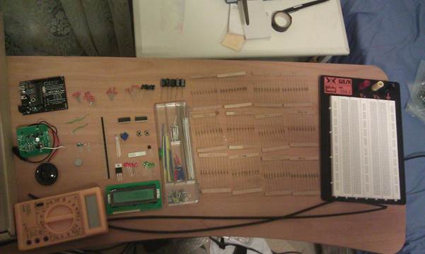
Figure 1 - Everything arrived by Wednesday 4th May 2011
Stage 2: Assembling LCD
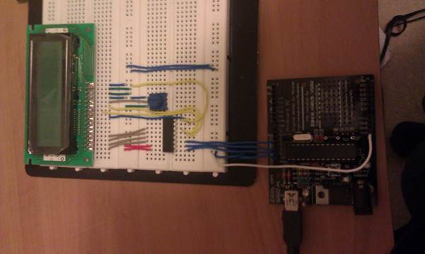
Figure 2 - Building LCD part of circuit, complete at 4.30am on Sunday, 8th May
Stage 2 involved building the LCD part of the circuit. For this I followed the tutorial and wiring instructions found in chapter 24 of John Boxall's Getting Started/Moving Forward with Arduino series (tronixstuff). Because my LCD screen had a different order in numbering, the version I used is in figure 4.
The LCD Section is split into 3 components, the 10k Potentiometer, the LCD Screen and the 4094 Register. The LCD Screen is a de facto industry standard HD44780 with 2 lines of 16 characters each. This particular one also has a backlight. The 4094 shift register is used because it has an existing library the (LCD3Wire) which comes pre-packaged with the Arduino 22 environment. The shift register allows us to display to the screen using only 3 digital pins as opposed to 7. Note pins 7-10 on the LCD screen aren't used because HD44780 screens can either be sent 4bit operations or 8bit operations. Since it is an entirely software thing, the less pins used the better.
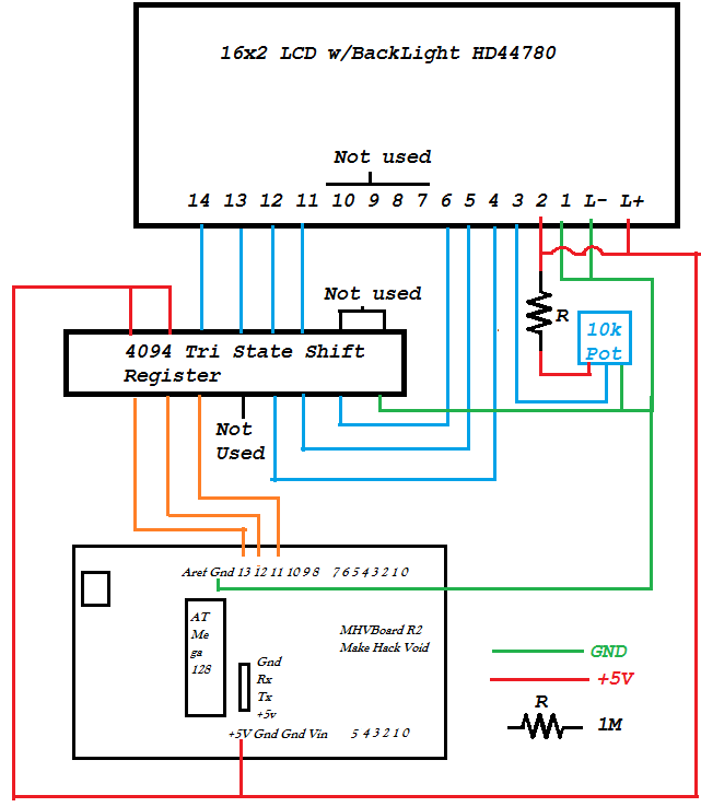
Figure 3 - LCD section of the circuit
The only issue faced was with the 10k potentiometer. The pot in this circuit is used as a contrast adjustor. On its own, with a 5V input, the output voltage ranges from 0V to 5V, however I found that for voltages above 1.5V, nothing on the screen was visible. I felt that this wasted 70% of the potentiometers range, and thus added the 1MΩ resister in series with Vin. If the Vout range goes from [Vmin, Vmax], then I found adding resistance in series with the ground increases Vmin. Adding resistance in series decreases Vmax. The 1M resister reduced the range to [0, 1.5V] which I found to be the best range of practicality. Note: I couldn't find this mentioned anywhere else when I tried to research it, so I'm not sure if it has any bad side effects- repeat with caution.
Stage 3: 3x3 LED Matrix
The LED matrix was originally going to just be 8 LEDs with an RGB in the middle, however the RGB was much brighter than the LEDs and doesn't fit in when the others are on. Thus an 9th 3mm LED was added, however it requires its own digital pin to work.
The matrix consists of 9 3mm LEDs, 8 of which are connected to a 74HC595 shift out register. The 74HC595 allows you to control 8 digital outs and set them to on or off based off a binary number (hence 8 bits). How it works is best explained here: http://www.arduino.cc/en/Tutorial/ShiftOut or in tronix tutorial chapter 4. A 0.1µF ceramic capacitor is also used to smooth the signal.
The relevant wiring for this section in my example is shown in figure 5.
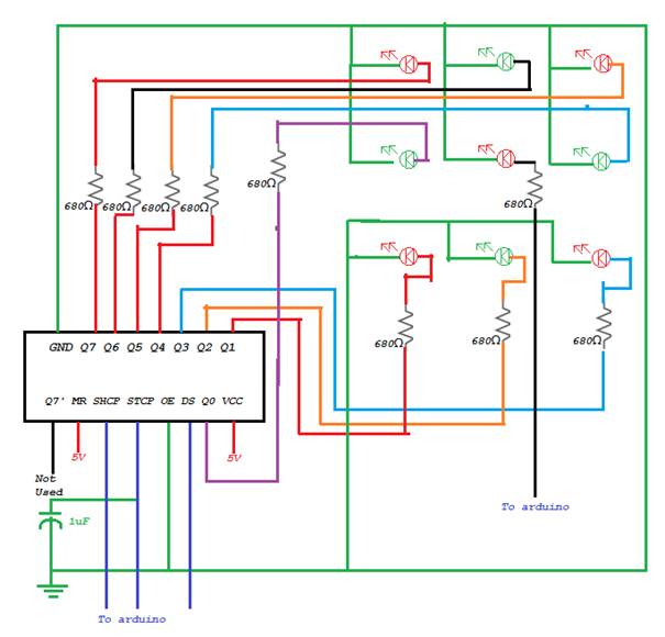
Figure 4 - 3x3 LED Matrix
Stage 4: RGB LED
There were a couple issues with the RGB led but those were resolved. It was suggested (Figure 5) to use an 180Ω resistor for R1, but as I didn't have any, so I used 2x100Ω resistors in series instead. It gives a total of 200, but I don't think it makes too much of a difference as it even with slightly less current the red is sufficiently bright.
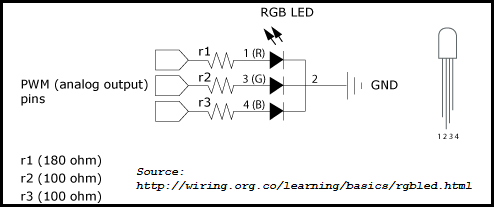
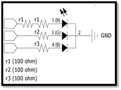
Figure 5 - Left: provided wiring instructions, Right: wiring used
Stage 5: Actuators
There are 4 sources of input for this system. 2 push buttons, 1 temperature sensor and a Wii nunchuck. The nunchuck adapter didn't require and further hardware, just need to plug the nunchuck in and it can be read via software. I didn't actually calibrate the temperature sensor so doesn't give reasonable values as of yet, but it is defined to be used only as a standby or idle screen which won't be implemented until later. The push buttons work, however I only have enough ports for one at a time. This is because for some reason port 7 doesn't work on my MHV board and instead it seems to short circuit and restart the board. In future, the working push button will be used as an interrupt and the wii nunchuck is meant to be used to navigate the menu.
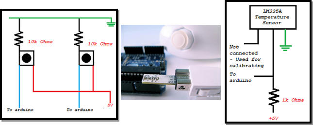
Figure 6 Push buttons, Nunchuck and Temperature Sensor. Source for nunchuck image: http://todbot.com
Final Result
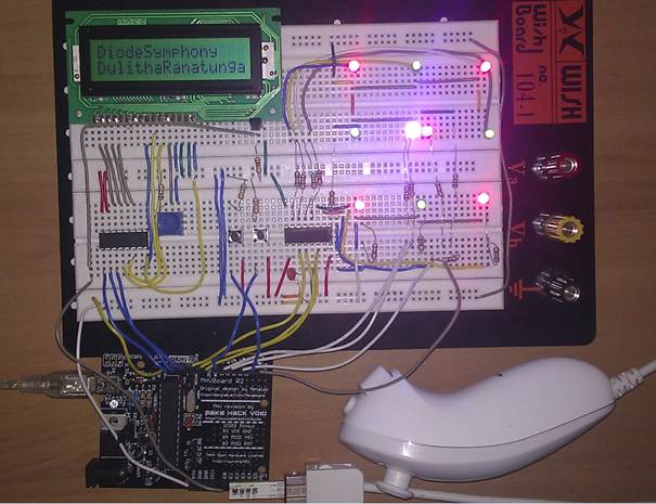
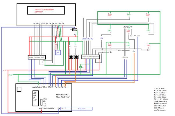
Figure 7 - Final product and full wiring diagram: all red lines are +5V and green lines are GND
Software Implementation - Arduino
LCD screen:
To get the LCD screen to work, I use the LCD3Wire library because we have a shift register in use. This is fairly simple to set up, and there are 3 main functions used:
lcd.cursorTo() moves the cursor to a line and a point
lcd.printIn() prints to the location of the cursor
lcd.clear() clears the screen
However there isn't an easy way to print integers, so I made a function 'printInt' which converts an integer into a char array and prints to location
Other functions that the LCD screen use include lcdPrintOneAtATime, which prints a string one character at a time with a delay. As well as helper functions such as printToLine and lcdDisplay to save me writing out lcd.cursorTo and lcd.printIn multiple times.
countdown() counts down from a given number, welcome() prints a splash screen to the LCD.
3x3 LED Display:
The middle LED is connected directly to the board, so its controlled using digitalWrite(port, HIGH or LOW). The other 8 LEDs are controlled using the shiftOut() function built into the arduino IDE. However before shiftOut() can be called, the 595 shift register needs to be told to receive input. This is done by turning the shiftlatch (STCP) pin on (digititalWrite(shiftlatchpin, LOW)). The shiftout function turns on the LEDs based off the binary bit pattern of a number in the range (0-255) [8 bits, each bit turns on or off, 2^8 = 256].
I made a few different functions to do effects with these LEDs, the functions blinkOuter, circleAround, fromCorner and spreadFromCenter all do a defined sequence of lighting. lightInOrder is a helper function that given a series of numbers will turn on the 9 LEDs in order accordingly.
RGB LED
The RGB led plugs directly into the analog pins of the board and uses the analogWrite() command. The only function I wrote for this is shiftRGB which transitions from one colour to another.
Inputs
The pushbuttons use digitalRead either high or low to determine when they are pressed. Currently they're used to start the program, but later they will change to use interrupts and bring up a menu system.
The temperature sensor connects to an analog input pin and can be read via analogRead. Its value can be displayed to the LCD screen using printInt.
The nunchuck gives a lot of software inputs. It uses the nunchuck_funcs library by Tod Kurt, and allows access to read joystick values (which range from 0 to 255 in both x and y, where (128,128) is the center/default). In the future the joystick controls will navigate a menu. The library also gives access to the z and c buttons as well as accelerometer readings.
Software Implementation - Java
As my project involves interfacing software with hardware, it would be pointless if I didn't have a user interface. The user interface is written in java and consists of many buttons as shown in figure 8 below. The original plan was to have the buttons turn the lights on in real time, but this requires a TTL to USB-Serial convertor cable which I did not get. Instead I decided to change the design so you don't get a real time response and instead it saves your keystrokes to be played back many times. When the menu system is made, it would ideally store a few songs in memory. The java program generates Arduino/C source code and saves it in a new file with the name of your song. This new file can then be opened and uploaded to be played on the board.
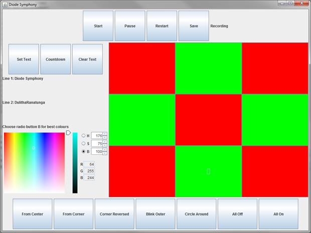
Figure 8 GUI for Diode Symphony
Other considerations and the future
The MHV Board uses an Atmel ATMega328P microprocessor with 32Kbyte flash memory. 2 Kbyte of which is SRAM. Using the shiftRGB function takes 214 bytes while time the matrix LEDs are turned on or off takes another 20bytes (optimal), 88 (worst case). Since these functions are called a few hundred times during a typical song (average length 4 minutes). There is a limitation on how many songs / how long a song can be stored on the chip at one time. Thus the java program should possible put checks in place as it doesn't at the moment. Currently I have gone up to 29KB in one song, which is dangerously bad.
Possible Improvements/new features:
- Working menu system with multiple songs
- Defensive programming of flash memory usage
- Possible get a TTL-Serial cable and enable a live play option
- Add a virtual screen so hardware is not necessary to see it working
- Nunchuck control mode
- Special LCD effects using custom characters
- Temperature sensor to actually do something useful.
- Moveable UI objects for others who wish to use the same program but with different layout
- Gesture supported colour wheel for RGB/ replace colour swatch.
Research
In order to undertake this project, considerable research was done the limitation of the MHVBoard and the ATMega328P micro controller as well as the Arduino. I read the book "Getting Started with Arduino" by Massimo Banzi as well as numerous tutorials on the arduino.cc reference library. The focus of my research was mainly on the cost vs. functionality of certain components and the simplest way of using them in the way I wanted. Judging by the tutorials I found, it seemed that the best way to get into the world of physical computing was to the just get parts and plug them in. Thus I bought a range of components and put them all on a breadboard to see what I could make.